
Introduction
A while back, I acquired Samsung’s SmartThings hub, along with some smart bulbs and a Google Home Mini, which allows me to control the lights in my room from my phone or with my voice. I wanted to start integrating other devices into this smart home system, and continuing with the trend of controlling lighting I decided to start with the blinds on my windows.
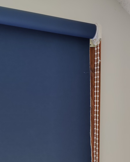
My blinds are roller blinds, and so the easiest way to automate them was to add a wheel that rotated the link chain in the desired direction to raise and lower the blinds. I wanted to keep the blinds I had, ruling out many available products, and those products that integrated with existing blinds were often over $100 for a single blind, slow, and required their own hub instead of integrating with what I had. I decided that since all I really needed was a way to turn a motor, this would be a great project to tackle myself.
Hardware
Motor and Power
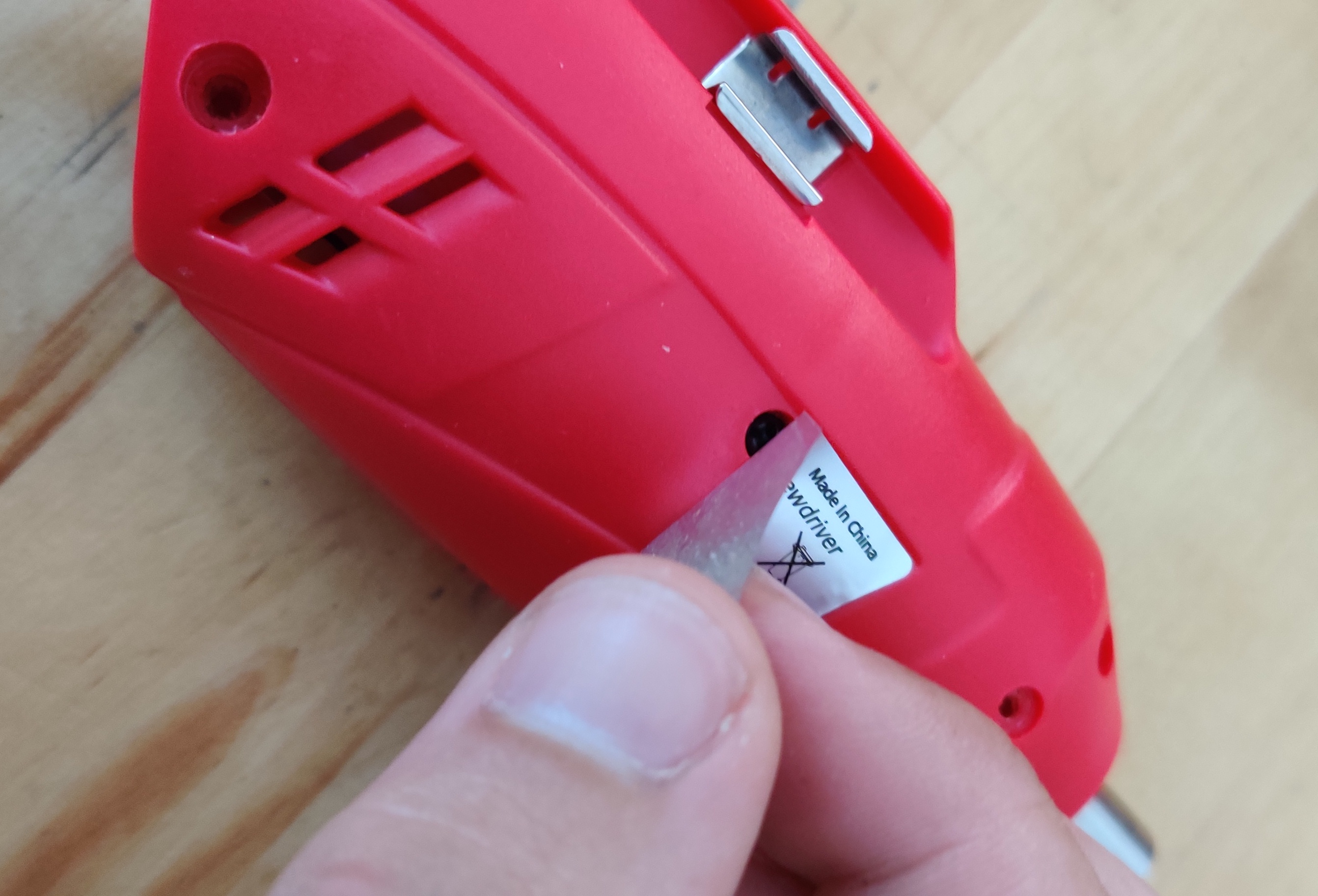
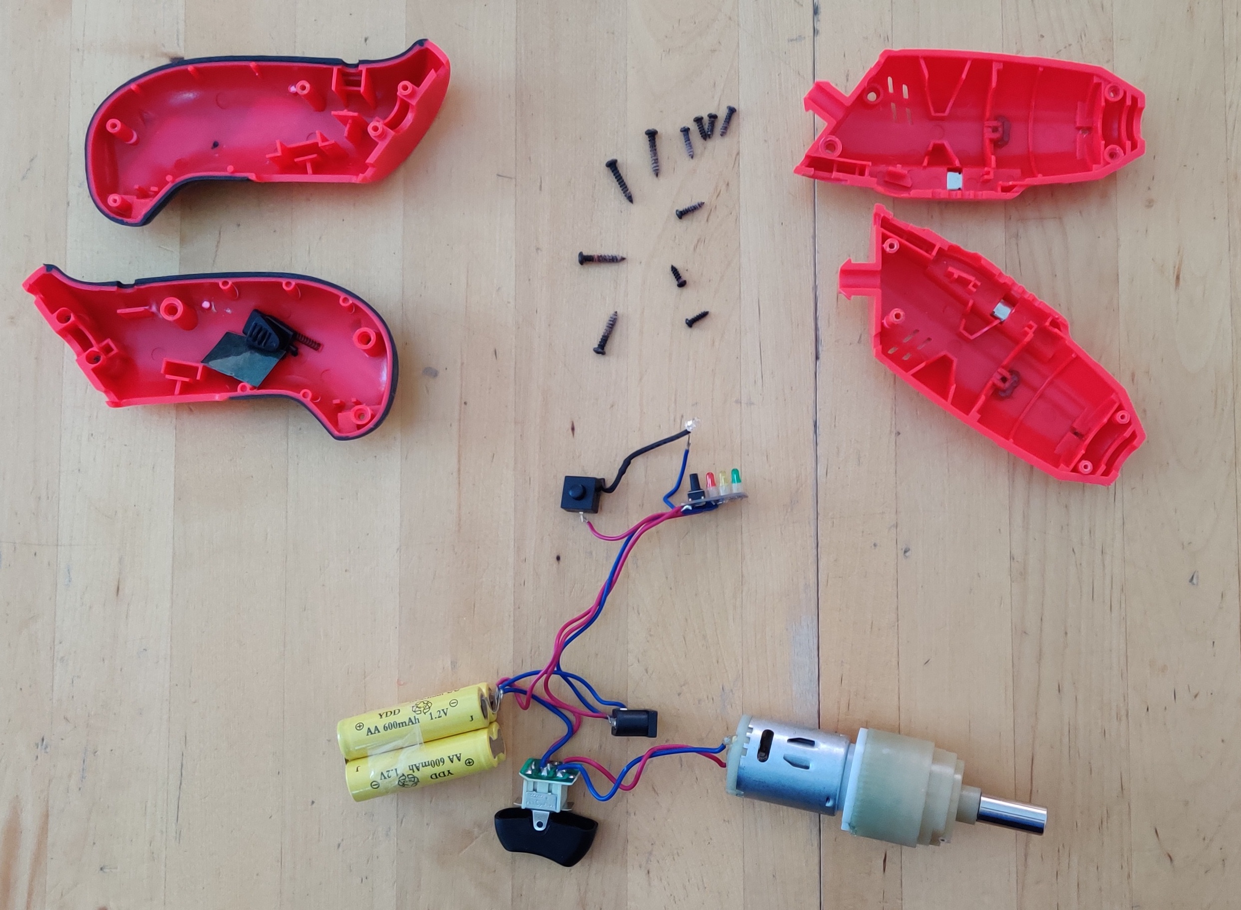
The first order of business was to find a motor. While once can buy individual motors, batteries, etc. online, I often gravitate towards using cordless rechargeable screwdrivers (I used this one) as they provide a strong motor, compatible battery, charging circuit, and charger all in one package, often cheaper than it would be to order and ship each component, and certainly easing power management concerns. I disassembled the screwdriver,
and was left with the motor, a battery pack, a charging port, and a charge indicator, all already wired together. Two other lucky benefits:
- The screwdriver is already wired to turn in both directions. I just need to replace the DPDT switch, but all the wires are present.
- The screwdriver contains additional wiring for an LED flashlight. I can use this to provide power to my microcontroller that is separated from the motor power.
Controlling the Motor
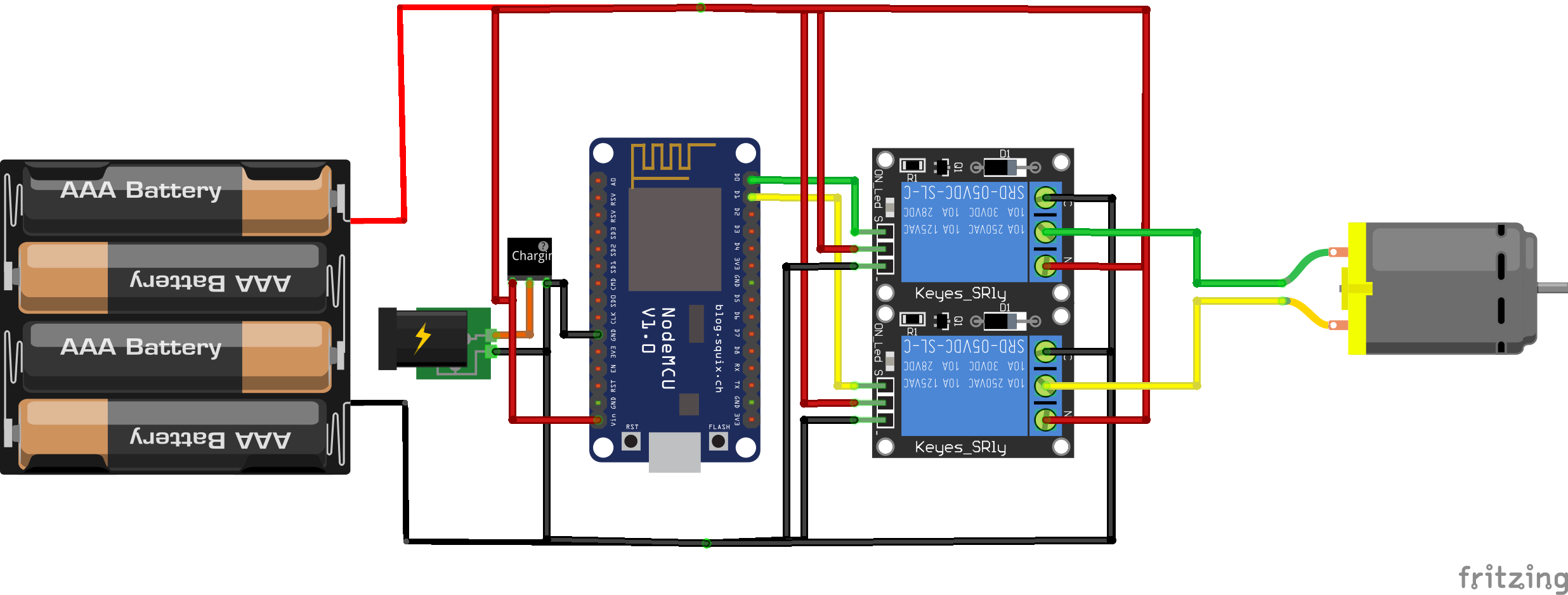
Now that I had the motor assembly, I had to replace the switch from the screwdriver with something that I could control from a microcontroller of some sort. Since the motor may be operating at a higher current and voltage than the microcontroller can handle directly, I used a relay. Once again we need to provide for rotation in both directions, as well as no rotation, for which we use two SPDT relays.
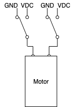
When both relays are off, the motor receives no power and is off. Turning on the left relay supplies power to the left motor terminal while leaving the right terminal grounded, completing the circuit. Turning on the right relay supplies power to the right motor terminal, while the left is grounded, causing the motor to turn the opposite direction. The fourth state (on, on) is not used, as we have four relay states but only three motor states.
Controlling the Relay
To complete the hardware setup, I needed a microcontroller that would send signals to the relays, and was able to somehow communicate with the SmartThings platform. I decided on an ESP8266, and found the NodeMCU Development Kit to fit my needs. While I did not take advantage of much of the NodeMCU firmware or use Lua for this project, the single-board development kit made for easy prototyping, and integrated nicely with the arduino tools I was familiar with.
To connect the MCU, I simply wired the screwdriver’s LED power to VIN, LED Ground to GND, connected those same pins to the relay VCC and GND, and then connected D0 and D1 to relay IN1 and IN2
Interfacing with the Blinds
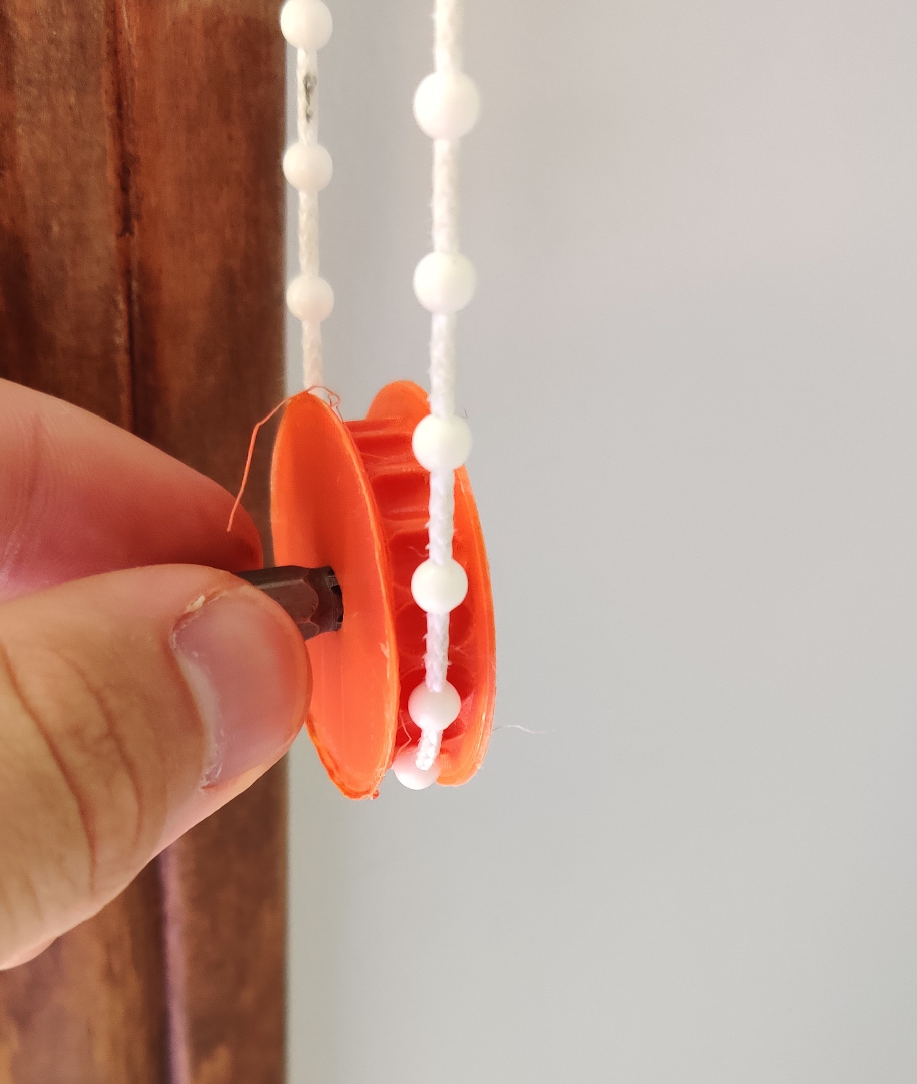
Now that I had a microcontroller-controlled motor, the last step was to connect it to the blinds. I took some measurements, hopped into Fusion 360, and designed and 3D-printed a wheel that the link chain would lock into. By placing a phillips hole in the middle of the wheel, I was able to mount it to the motor by simply inserting a phillips bit into the wheel and motor, once again taking advantage of the features of the cordless screwdriver.
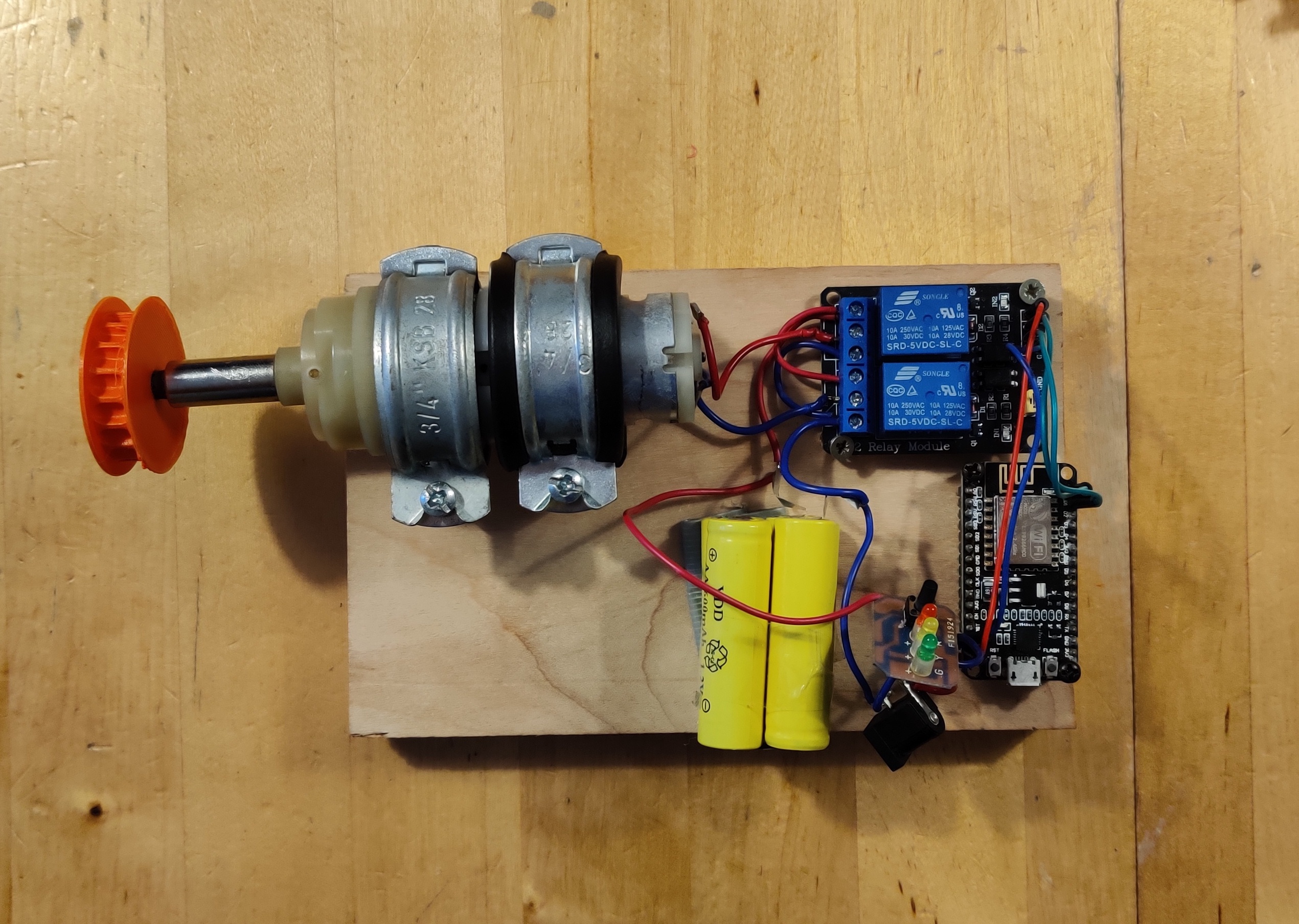
All that was left to do was to mount the motor, battery pack, and boards using some brackets, screws, and duct tape, and I was ready to program and test my prototype.
Software
NodeMCU Firmware
The first order of business on the microcontroller side of things was to be
able to control the motor via the relays. To do this, I had to activate one of
the relays to turn the motor in that direction. The relay connects when a LOW
signal is sent.
#define OPEN_PIN 16 //D0
#define CLOSE_PIN 5 //D1
#define ON_TIME 1000

void setup(void){
	pinMode(OPEN_PIN, OUTPUT);
	pinMode(CLOSE_PIN, OUTPUT);
	digitalWrite(OPEN_PIN, HIGH);
	digitalWrite(CLOSE_PIN, HIGH);
	//...
}
void open(void){
	Serial.println("Opening");
	digitalWrite(OPEN_PIN, LOW);
	delay(ON_TIME);
	digitalWrite(OPEN_PIN, HIGH);
}

void close(void){
	Serial.println("Closing");
	digitalWrite(CLOSE_PIN, LOW);
	delay(ON_TIME);
	digitalWrite(CLOSE_PIN, HIGH);
}
Now that I had an easy way to control the motor, I needed to connect the board
to the internet. Eventually, the goal was to have an HTTP request to <board
IP>/open open the blinds, and a call to /close close them.
I began with the ESP8266 WiFi Library which allows the MCU to connect to my home WiFi:
#include <ESP8266WiFi.h>

const char* ssid = "REDACTED";
const char* password = "REDACTED";

void setup(void){
	//...
	Serial.begin(9600);
  Serial.println();
  WiFi.begin(ssid, password);

  // Wait for connection
  while (WiFi.status() != WL_CONNECTED) {
    delay(500);
    Serial.print(".");
  }
  Serial.println();

  Serial.print("Connected to ");
  Serial.println(ssid);
  Serial.print("IP address: ");
  Serial.println(WiFi.localIP())
	//...
}
Next we use the ESP8266WebServer Library to serve our endpoints. Since we are serving a website anyways, we also add some buttons so that we can control the blinds from the web without SmartThings integration. This server is only accessible locally.
#include <ESP8266WebServer.h>

// Create server and listen on port 80
ESP8266WebServer server(80);

void setup(void){
	//...
	server.on("/", [](){
    server.send(200, "text/html", webPage);
  });
  server.on("/open", [](){
    server.send(200, "text/html", webPage);
		open();
  });
  server.on("/close", [](){
    server.send(200, "text/html", webPage);
    Serial.println("Closing");
		close();
  });
  server.begin();
  Serial.println("HTTP server started");
}

void loop(void){
  server.handleClient();
}
Running after the WiFi connection is established, this code sets up the server to serve the simple website, which we define as follows:
<h1>Smart Blinds</h1>
<p>Blinds #1
	<a href=\"open\">
		<button>Open</button>
	</a>
	<a href=\"close\">
		<button>Close</button>
	</a>
</p>
(Note in the code this is concatenated into one long String)
This website is served at the root path /. When the user clicks on one of the
buttons, or otherwise navigates to the /open or /close endpoints, we send
that same webpage so they may continue control, and execute the corresponding
open() or close() function.
Lastly, we want to be able to access our server without having to know the exact IP, so we use multicast DNS (mDNS) via the ESP8266mDNS Library
#include <ESP8266mDNS.h>
MDNSResponder mdns;

void setup(void){
	if (mdns.begin("SmartBlinds", WiFi.localIP())) {
		Serial.println("MDNS responder started");
	}
}
This allows us to access our server at http://SmartBlinds.local rather than
needing to know the exact IP.
The full code is available on my GitHub.
SmartThings Device Handler
Now that our blinds are fully operational, we just need to integrate them with the SmartThings ecosystem. This is accomplished by writing our own device handler, adapted from a Generic HTTP Device. Once again, the full code is on GitHub, but I will highlight some of the important parts:
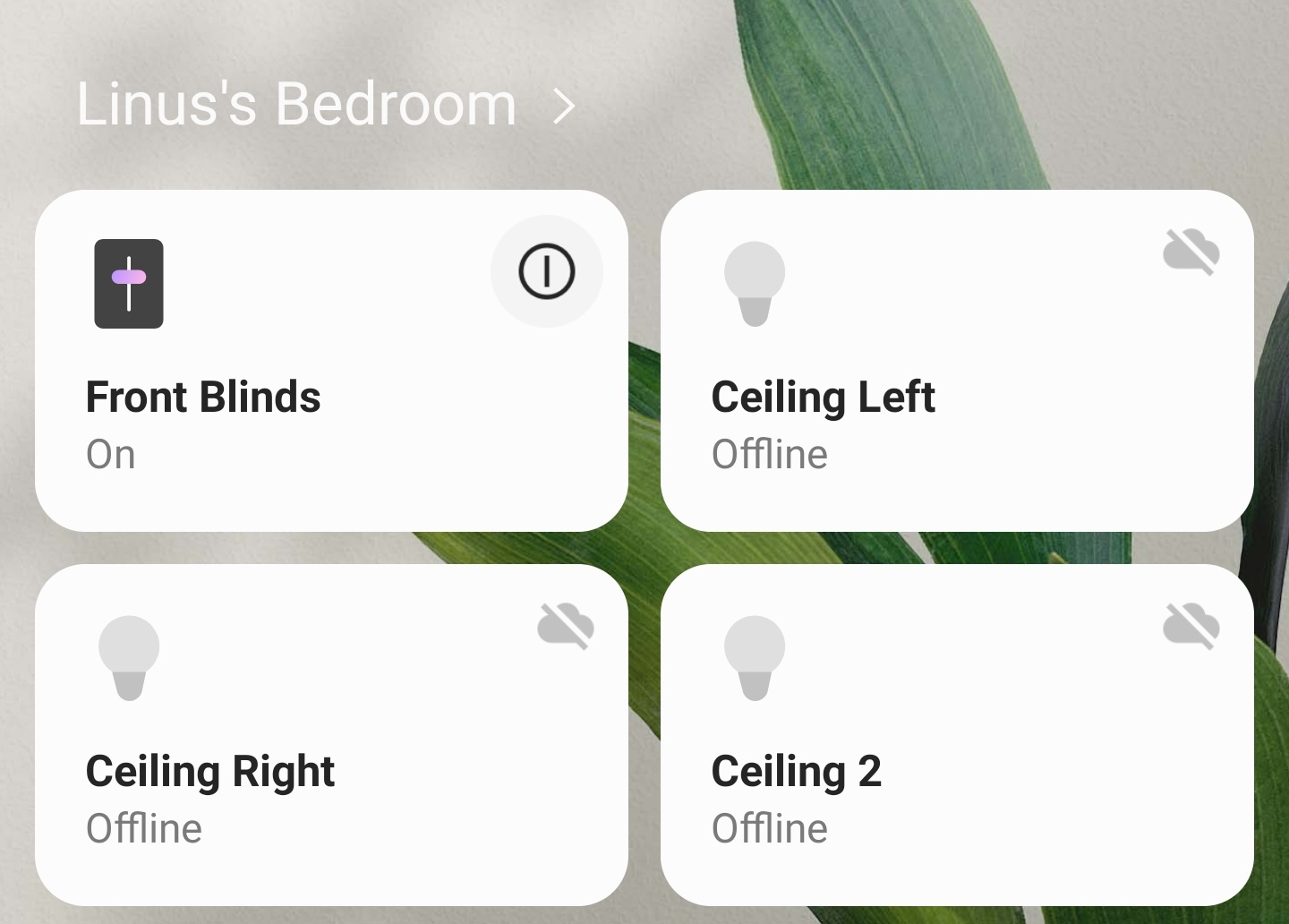
We define a UI with a single tile, that has actions on and off.
tiles {
	standardTile("DeviceTrigger", "device.triggerswitch", width: 3, height: 3, canChangeIcon: true, canChangeBackground: true) {
		state "triggeroff", label:'CLOSED' , action: "on", icon: "st.Weather.weather4", backgroundColor:"#808080", nextState: "trying"
		state "triggeron", label: 'OPEN', action: "off", icon: "st.Weather.weather14", backgroundColor: "#ffffff", nextState: "trying"
		state "trying", label: 'TRYING', action: "", icon: "st.Home.home9", backgroundColor: "#FFAA33"
	}
	main "DeviceTrigger"
}
These actions call methods which send an event back to the hub to trigger the UI
change, and then execute the runCMD method.
def on() {
	log.debug "Triggered OPEN!"
		sendEvent(name: "triggerswitch", value: "triggeron", isStateChange: true)
		state.blinds = "on";
	runCmd("/open")
}
// Similar for off() -> /close
This method then makes the http request.
def runCmd(String varCommand) {
	def result = new physicalgraph.device.HubAction(
			method: "GET",
			path: varCommand,
			headers: [
				HOST: "$DeviceIP:80"
			]
			)
		log.debug result
		return result
}
Sadly SmartThings does not support mDNS resolution, so we must specify the device IP, which may change. However, mDNS makes it easier to retrieve that IP from a computer on the network.
Conclusions
I always love projects that mix software and hardware, and this one covered everything from building circuits to designing what is essentially an API. I was pleasantly surprised with the amount of developer support and documentation for the SmartThings platform, which allowed for easy extensibility, and it feels much more legitimate to see the control for the blinds alongside all the other controls on my phone.
My first experience with a WiFi enabled microcontroller was also very pleasant. Although I am iffy about setting the html being served as a single string constant, the process of setting up a web server and handling different routes was made fairly simple by the provided libraries.
All in all, this was a fun home automation project, and I look forward to working more with the NodeMCU and the SmartThings platform in the future.